Lecture 6: CPUs


(Originally recorded 2019-04-18)
In this lecture we develop a simple model for CPU operation that we use to motivate a sequence of optimizations for matrix-matrix product.
Microprocessors
The first step in getting high levels of performance from a computation is getting high performance from the component at the bottom of the stack – namely the microprocessor.
Modern microprocessors are exceedingly complex and are marvels of modern engineering. The following images show a block diagram of the Intel Skylake microprocessor architecture as well as a photograph of the actual processor die.
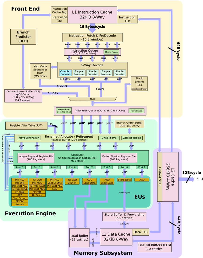
Block architecture diagram of Intel Skylake microprocessor.
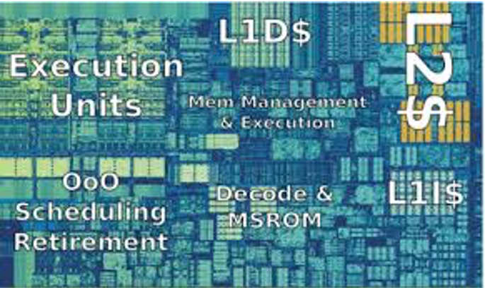
Photograph of Intel Skylake microprocessor die.
For the purposes of writing programs to make effective use of a microprocessor, we can consider an idealized abstract model consisting of an execution unit, registers, two levels of cache, and main memory.

Abstract microprocessor model for AMATH 483/583. From left to right the model consists of an execution unit, registers, two levels of cache, and main memory.
Basic Operation
We now build up to the abstract model above.
All events in a microprocessor are governed by a clock. The clock is an electrical signal that goes up and down at some frequency – the clock rate. A 2GHz clock goes up and down two billion time per second. A typical microprocessor is comprised of hundreds of millions of functional units that all need to work together in a coordinated fashion to properly carry out the CPU’s operations. The clock signal is what keeps all of those parts in sync. Each time the clock rises (or falls), the functional units in the CPU are allowed to take one step – all together. The faster the clock, the faster the CPU can take its processing steps.
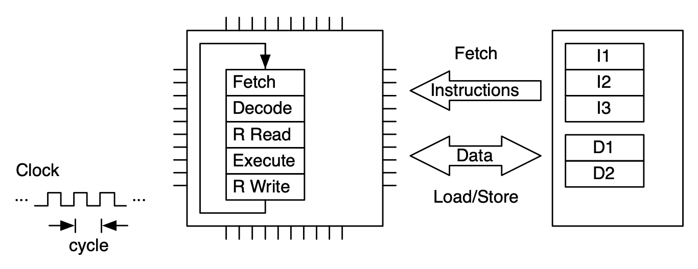
The basic sequence of steps that a microprocessor can take is: fetch an instruction from memory and execute the instruction. A computer program consists of a sequence of binary machine instructions that are stored in computer memory. A special register in the microprocessor points to the next location in memory to fetch an instruction. Once an instruction is fetched, the program counter is updated to point to the next instruction to be fetched.

Most basic model for a CPU. The basic operation of the CPU is to fetch an instruction from memory (the cells denote with “I”) and then to execute that instruction.
Instructions are not executed by the microprocessor in one fell swoop. Rather, there are multiple stages that the instruction needs to move through for its execution. One simple model of those stages for an arithmetic operations is:
Fetch: The instruction is fetched from memory and brought to the CPU
Decode: The instruction is read and decoded
Read: The data needed for the instruction are read from registers
Executed: The decoded instruction is executed
Write: The results of the executed instruction are written back to registers
Non-arithmetic instructions (that are stil processed in a pipeline) are to load a datum from memory into a register, to store a datum from a register to memory, or to change the value of the program counter to point somewhere else in the program. (This last kind of instruction happens when program execution branches, for example when a function is called, or an if statement is executed.)
Model of CPU with Fetch-Decode-Execute (FDE) unit. This unit has five stages.
An instruction is processed by moving through the FDE unit. The instruction advances one stage at each clock cycle. In this case multiple clock cycles are needed to process just one instruction.
To make more efficient use of the FDE (and thus the microprocessor), sequences of instructions are processed in pipeline fashion. This allows up to one instruction to be completed per clock cycle (on average).
Hierarchical Memory
There is one big flaw in our model as it is. In the figure above where we have instructions nicely pipelined one after the other, we are assuming that instructions can be fetched from computer memory in a single clock cycle. In fact, accessing main memory can take hundreds of clock cycles – making it impossible to fill the instruction pipeline (and making pipelining as a performance optimization rather moot).
Modern microprocessors use a memory hierarchy to ameliorate the cost of memory accesses. In particular, they are constructed with memory that is very fast – that can be accessed in a single clock cycle. This kind of memory is necessarily expensive, so it is much smaller than main memory. The fastest cache, the first level or level one (L1) may only be tens of **kilo**bytes in size (where main memory today is gigabytes). The cache keeps data that the microprocessor is most likely to access close to the microprocessor, making those accesses highly efficient. Since not all of the data a microprocessor may want to access can be held in the small L1 cache, there is a much larger but not quite as fast level two cache – and often a level three or even level four – each level being larger but slower than the previous level. Microprocessors typically have a separate L1 cache for instructions and data (since their access patterns at that level of granularity are quite different) but unified L2 and above. L3 and L4 (if present) may be shared between cores on the same die.
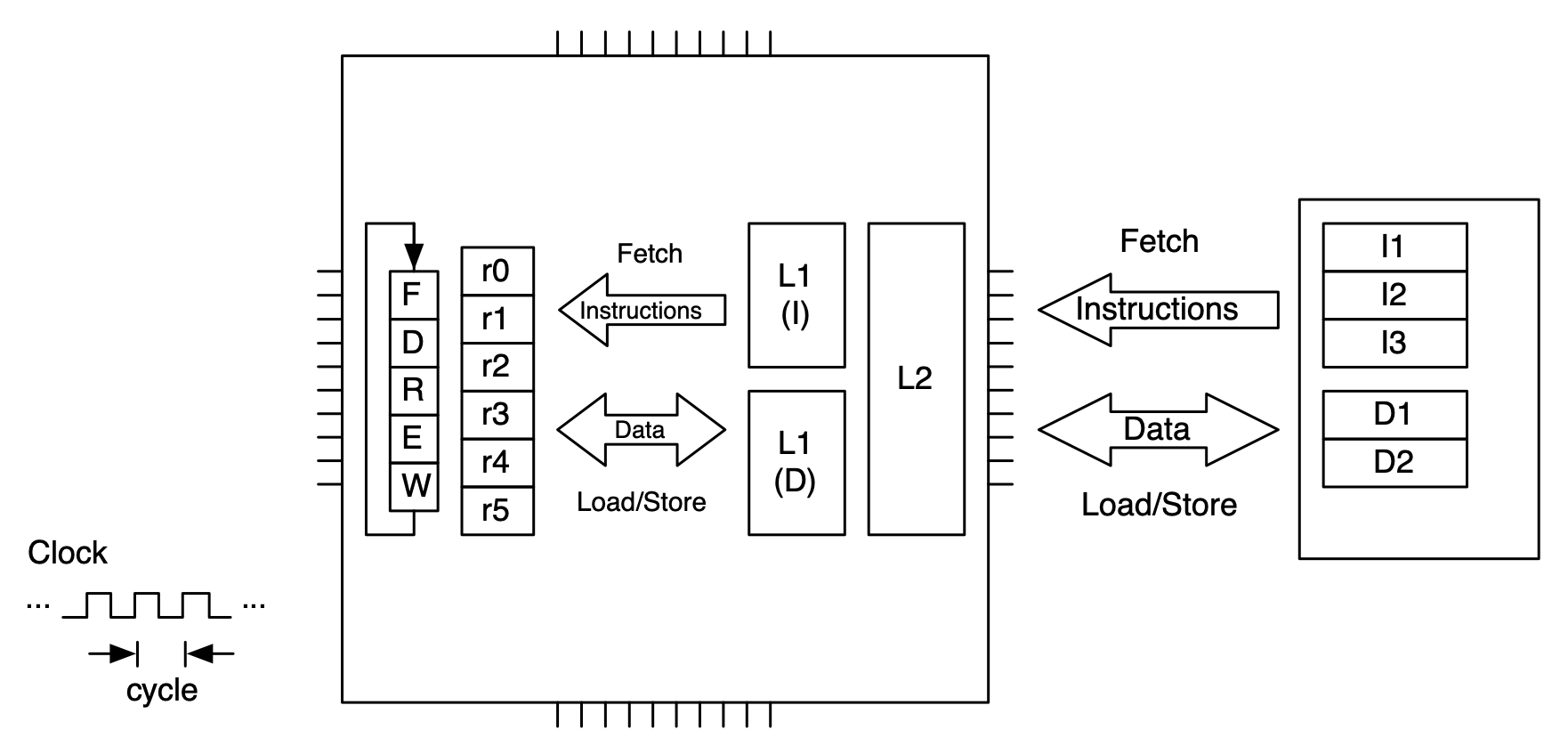
Memory hierarchy for a single core processor.
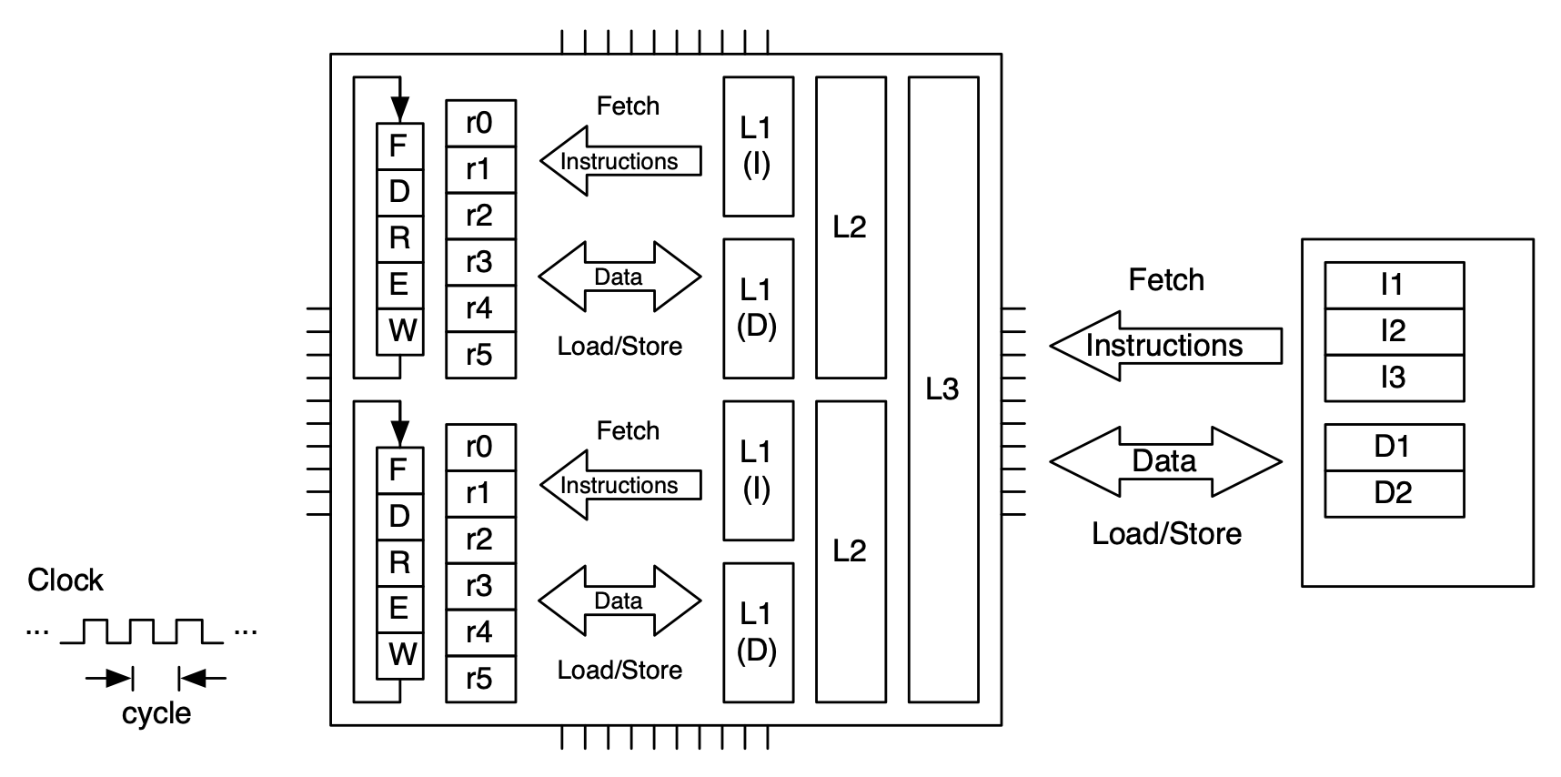
Memory hierarchy for a dual core processor. The level 3 cache is shared between the cores (as is main memory).
A microprocessor uses its cache in the following way. When it needs something from memory, either an instruction or a data item, it first attempts to retrieve the item from L1 cached. If the item is not in L1, it attempts to retrieve it from L2. If it is not in L2, it attempts to retrieve it from L3 and so on. If the item cannot be found in any level of cache, there is a cache miss and the item is retrieved from memory.
What happens when the item is retrieved from memory is very important vis a vis performance. There is an important concept in dealing with hierarchical memory called locality. There are two kinds of locality – spatial locality and temporal locality. Spatial locality means that if we access a data item, the next data item we access is likely to be nearby in memory. Temporal locality means that if we access a data item, we are likely to access that item again.
So, when there is a cache miss and the item is retrieved from memory we do two things to support spatial and temporal locality. First, we put the item into cache, so that the next time we access that item it will be cached (temporal locality). Second, we don’t just bring in the item that was requested — we bring in that item along with data items that are nearby in memory (spatial locality). The size of that access is sized to fit a cache line, which might be 64 or 128 bytes (or more).
Performance Optimization
Hierarchical memory allows microprocessors to offer very high levels of performance, despite the fact that accesses to main memory are much slower than the rate at which instructions can be executed. This level of performance is possible when applications fulfill the assumptions underlying hierarchical memory, i.e., when applications exhibit high levels of temporal and spatial locality. Our task in realizing high-performance scientific computing is to develop and express our algorithms in such a way that they do exhibit maximum locality.